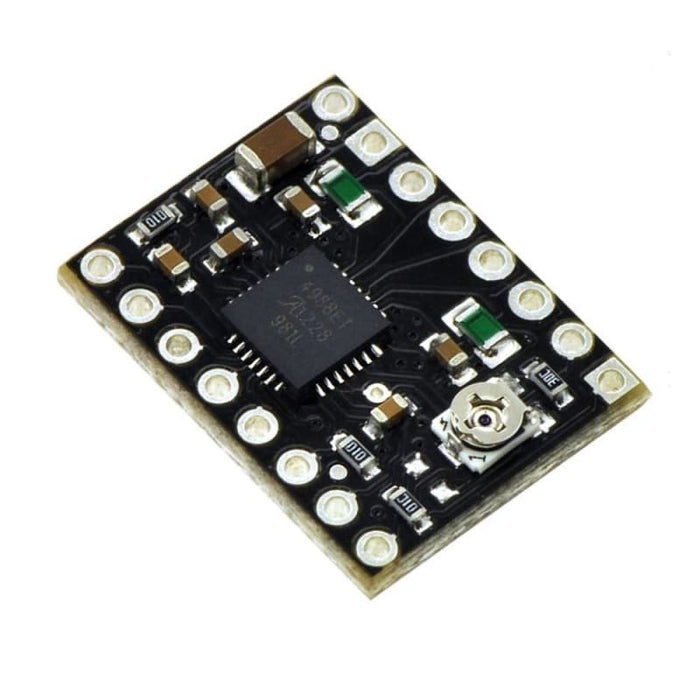
Stepper Motor Driver A4988 Carrier - Black Edition
£11.66 ex VAT
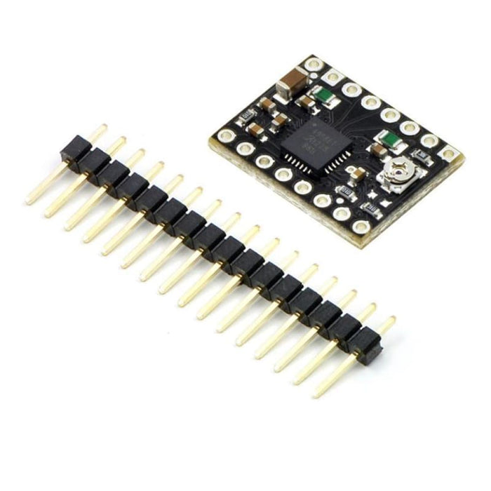
The Black Edition A4988 stepper motor driver carrier is a higher-performance drop-in replacement for the original A4988 stepper motor driver carrier. It features a four-layer PCB for better thermal performance, allowing the A4988 micro stepping bipolar stepper motor driver to deliver approximately 20% more current than the two-layer (green) version. Like the original carrier, the Black Edition offers adjustable current limiting, over-current and over-temperature protection, and five different micro step resolutions. It operates from 8 V to 35 V and can deliver up to 2 A per coil with sufficient additional cooling. This board ships with 0." male header pins included but not soldered in.
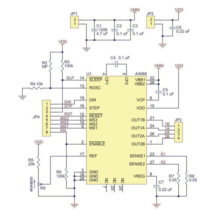
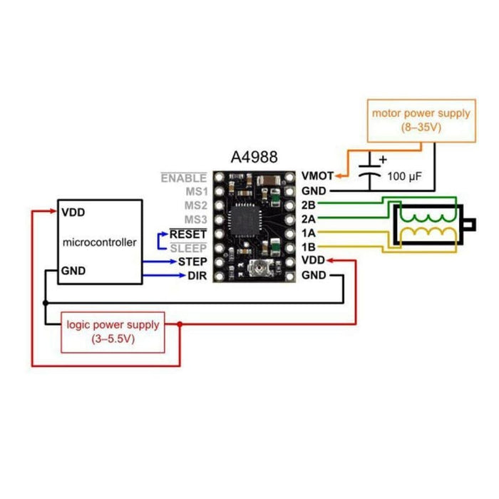
Power connections
The driver requires a logic supply voltage (3 “ 5.5 V) to be connected across the VDD and GND pins and a motor supply voltage (8 “ 35 V) to be connected across VMOT and GND. These supplies should have appropriate decoupling capacitors close to the board, and they should be capable of delivering the expected currents (peaks up to 4 A for the motor supply).
Step (and micro step) size
Stepper motors typically have a step size specification (e.g. 1.8° or 200 steps per revolution), which applies to full steps. A micros tepping driver such as the A4988 allows higher resolutions by allowing intermediate step locations, which are achieved by energizing the coils with intermediate current levels. For instance, driving a motor in quarter-step mode will give the 200-step-per-revolution motor 800 micro steps per revolution by using four different current levels. More details on micro stepping can be found on the datasheet.
Control inputs
Each pulse to the STEP input corresponds to one micro step of the stepper motor in the direction selected by the DIR pin. Note that the STEP and DIR pins are not pulled to any particular voltage internally, so you should not leave either of these pins floating in your application. If you just want rotation in a single direction, you can tie DIR directly to VCC or GND. The chip has three different inputs for controlling its many power states: RST, SLP, and EN. For details about these power states, see the datasheet. Please note that the RST pin is floating; if you are not using the pin, you can connect it to the adjacent SLP pin on the PCB to bring it high and enable the board.
Please Note:
- Four, six, and eight-wire stepper motors can be driven by the A4988. Some unipolar stepper motors (e.g. those with six or eight leads) can be controlled by this driver as bipolar stepper motors. Unipolar motors with five leads cannot be used with this driver.
- Measuring the current draw at the power supply will generally not provide an accurate measure of the coil current. Since the input voltage to the driver can be significantly higher than the coil voltage, the measured current on the power supply can be quite a bit lower than the coil current (the driver and coil basically act like a switching step-down power supply).
- If the supply voltage is very high compared to what the motor needs to achieve the set current, the duty cycle will be very low, which also leads to significant differences between average and RMS currents.
- Simple step and direction control interface
- Five different step resolutions: full-step, half-step, quarter-step, eighth-step, and sixteenth-step
- Adjustable current control lets you set the maximum current output with a potentiometer, which lets you use voltages above your stepper motor's rated voltage to achieve higher step rates
- Intelligent chopping control that automatically selects the correct current decay mode (fast decay or slow decay)
- Over-temperature thermal shutdown, under-voltage lockout, and crossover-current protection
- Short-to-ground and shorted-load protection
- 4-layer, 2 oz copper PCB for improved heat dissipation
- Exposed solderable ground pad below the driver IC on the bottom of the PCB
Specifications:
- Minimum operating voltage: 8 V
- Maximum operating voltage: 35 V
- Continuous current per phase:1.2 A Without a heat sink or forced airflow
- Maximum current per phase: 2 A With sufficient additional cooling
- Minimum logic voltage: 3 V
- Maximum logic voltage: 5.5 V
- Microstep resolutions: full, 1/2, 1/4, 1/8, and 1/16
- No reverse voltage protection
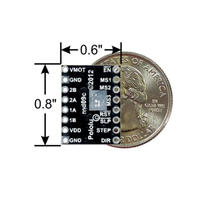
- Size: 0.6"— 0.8"
- Weight: 1.5 g